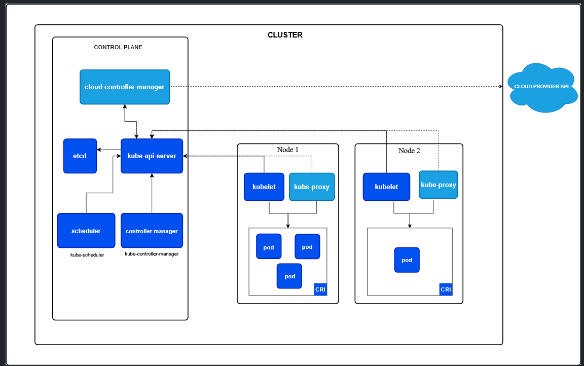
Kubernetes Architecture
The main task kubernetes does is — it manages containers, that’s it. It has many componentes involved to achieve the goal of managing and orchestrating containers in the best possible way but at its core, it’s just a container manager. Some strongest followers of technical words may surge up but believe me I am trying to keep it simple because Kubernets is easy. And we will see how each components works together to achieve the common goal.
Our goal is to understand architecture of kubernetes but by building it piece by piece.
Kubernetes Architecture
As kubernetes manages containers, now entering the world of kubernetes — let’s try calling pods and not containers. Kubernetes itself keeps it simple:
A Pod (as in a pod of whales or pea pod) is a group of one or more containers,…
We introduce pod. It needs some host to run inside, well call hosts as nodes here. There can be multiple pods in a single host.
    flowchart
    %% Worker
    subgraph NODE1["Node"]
        subgraph PODS["Pods"]
            P1["Pod"]
            P2["Pod"]
        end
    end
Node Components
Node components runs on every node which ensures pods are running.
Container Runtimes
Since, pods are just group of one more group of containers — the underlying technology that makes the container possible is the basic requrirement even with the kubernetes. After all, containers are what running. So, you can’t exclude container runtime from the picture. Runtimes can be anything that implements Kubernetes Container Runtime Interface (CRI) such as: containerd.
    flowchart
    %% Worker
    subgraph NODE1["Node"]
        subgraph PODS["Pods"]
            P1["Pod"]
            P2["Pod"]
        end
        CRT1["Runtime"]
    CRT1 --> PODS
    end
Networking (kube-proxy)
While minimal networking is possible with containers by using linux features, but there has to be something that provides advanced networking features to maintain network rules on nodes which allows communication in and out of the pods and even supports load balancing. kube-proxy is there for you. If services deployed in pods themself implemennts netwrok plugins that supports packet forwarding for services by itself, then this kube-proxy is optional. But still, something has to be there even to be optional.
    flowchart
    %% Worker
    subgraph NODE1["Node"]
        subgraph PODS["Pods"]
            P1["Pod"]
            P2["Pod"]
        end
        CRT1["Runtime"]
        PROXY1["kube-proxy"]
    CRT1 --> PODS
    PROXY1 --> PODS
    end
Monitoring (kubelet)
Someone has to ensure that the containers are running and healthy in a pod. kubelet monitors or make sures that containers are running according to the predefined PodSpecs (some specifications containers should adheres to) — this is what makes healing possible as it reports to API server on failure.
    flowchart
    %% Worker
    subgraph NODE1["Node"]
        subgraph PODS["Pods"]
            P1["Pod"]
            P2["Pod"]
        end
        CRT1["Runtime"]
        PROXY1["kube-proxy"]
        MONITOR1["kubelet"]
    CRT1 --> PODS
    PROXY1 --> PODS
    MONITOR1 --> PODS
    end
Control Plane Components
Node components are basically enough to run pods but for kubernetes to be an effective orchestrator — control place exists — the brain of kubernetes. This is where every decision are made such as where to start new container, how to react to cluster events, etc. Control plane components can be run on any node but many designs keep all control plane components on specific node called “master” and generally don’t run user containers here.
API Server (kube-apiserver)
Kubernetes exposes Kubernetes API server in the front end which can be scaled horizontally — basically add more of them if you need more kind. This is where request like creating pod, container health, etc. kube-apiserver decides when to create node and other decisions.
    flowchart
    subgraph CLUSTER["Cluster"]
        %% Master
        subgraph MASTER["Control Plane"]
            API["kube-api-server"]
        end

        %% Worker
        subgraph NODE1["Node"]
            subgraph PODS["Pods"]
                P1["Pod"]
                P2["Pod"]
            end
            CRT1["Runtime"]
            PROXY1["kube-proxy"]
            MONITOR1["kubelet"]
        CRT1 --> PODS
        PROXY1 --> PODS
        MONITOR1 --> PODS
        end

        MONITOR1 -.-> API
    end
Scheduler (kube-scheduler)
While API Server may decide to create pod, kube-scheduler is what watches for newly created pods and assign them to nodes to run on. It takes different factors into account while scheduling like: resource requirements, hardware constraints,etc.
    flowchart
    subgraph CLUSTER["Cluster"]
        %% Master
        subgraph MASTER["Control Plane"]
            API["kube-api-server"]
            SCHEDULER["kube-scheduler"]
        end

        %% Worker
        subgraph NODE1["Node"]
            subgraph PODS["Pods"]
                P1["Pod"]
                P2["Pod"]
            end
            CRT1["Runtime"]
            PROXY1["kube-proxy"]
            MONITOR1["kubelet"]
        CRT1 --> PODS
        PROXY1 --> PODS
        MONITOR1 --> PODS
        end

        MONITOR1 -.-> API
        %%PROXY1 -.-> API
        SCHEDULER --> API
    end
Controller Manager (kube-controller-manager)
Kubernetes supports various features like auto scaling, firewalls, etc. There are basically several controllers for specific tasks for example: node controller is responsible for noticing and responding when nodes go down, replica set controller for auto scaling, etc. And somebody has to monitor these all cotrollers are running and doing what they are intended to do — kube-controller-manager does that. Actually, each controller is a separate process but they are all compilied into a single binary for simplicity to run in a single process. Let’s not go there.
    flowchart
    subgraph CLUSTER["Cluster"]
        %% Master
        subgraph MASTER["Control Plane"]
            API["kube-api-server"]
            SCHEDULER["kube-scheduler"]
            CTRL_MGR["kube-controller-manager"]
        end

        %% Worker
        subgraph NODE1["Node"]
            subgraph PODS["Pods"]
                P1["Pod"]
                P2["Pod"]
            end
            CRT1["Runtime"]
            PROXY1["kube-proxy"]
            MONITOR1["kubelet"]
        CRT1 --> PODS
        PROXY1 --> PODS
        MONITOR1 --> PODS
        end

        MONITOR1 -.-> API
        SCHEDULER --> API
        CTRL_MGR --> API
    end
Data Storage (etcd)
Cluster data or information has to be somewhere to keep into and retrieve from which has to be consistent and highly available. Kubernetes uses etc as the backing store. Kubernetes also suggests to have backup plan when using etcd:
If your Kubernetes cluster uses etcd as its backing store, make sure you have a back up plan for the data.
    flowchart
    subgraph CLUSTER["Cluster"]
        %% Master
        subgraph MASTER["Control Plane"]
            API["kube-api-server"]
            SCHEDULER["kube-scheduler"]
            CTRL_MGR["kube-controller-manager"]
            ETCD["etcd"]
        end

        %% Worker
        subgraph NODE1["Node"]
            subgraph PODS["Pods"]
                P1["Pod"]
                P2["Pod"]
            end
            CRT1["Runtime"]
            PROXY1["kube-proxy"]
            MONITOR1["kubelet"]
        CRT1 --> PODS
        PROXY1 --> PODS
        MONITOR1 --> PODS
        end

        MONITOR1 -.-> API
        SCHEDULER --> API
        CTRL_MGR --> API
        API <--> ETCD
    end
Cloud Controller Manager — CCM (cloud-controller-manager)
There is another concept in kubernetes as cloud-controller-manager. Kubernetes can run on cloud take it AWS, Azure, Google, etc. But CCM is what makes it possible. For example: if you send request to kubernetes to create some nodes or deploy pods, kubernetes has to understand all underlying resources of the cloud and communicate between them to manage resources. To put it simple, it has to translate user request to something what cloud understands. This translation should be implemented on CCM.
Let’s try to understand it with a concrete example. Assue you create your cloud platform ABC and you want kubernets as service inside your cloud. Kubernetes can’t write the logic to implement the “translation” for you. It says: Hey! I can’t write this logic for you but I provide you this CCM, this is open source — you write your logic inside here and open pull request. This is how you integrate kubernetes in your cloud platform.
Cloud Controller Manager (CCM) is the Kubernetes control-plane component that contains cloud-provider-specific logic, allowing Kubernetes to interact with a particular cloud’s APIs without putting that cloud-specific code into Kubernetes core.
If you are running on-premise infra, no need to worry about CCM at all — such cluster does not have a cloud controller manager.
    flowchart LR
    CLOUD@{ shape: cloud, label: "Cloud Provider API"}
    subgraph CLUSTER["Cluster"]
        %% Master
        subgraph MASTER["Control Plane"]
            API["kube-api-server"]
            SCHEDULER["kube-scheduler"]
            CTRL_MGR["kube-controller-manager"]
            ETCD["etcd"]
            CLOUD_CTRL_MGR["cloud-controller-manager"]
        end

        %% Worker
        subgraph NODE1["Node"]
            subgraph PODS["Pods"]
                P1["Pod"]
                P2["Pod"]
            end
            CRT1["Runtime"]
            PROXY1["kube-proxy"]
            MONITOR1["kubelet"]
        CRT1 --> PODS
        PROXY1 --> PODS
        MONITOR1 --> PODS
        end

        MONITOR1 -.-> API
        SCHEDULER --> API
        CTRL_MGR --> API
        API <--> ETCD
        API <--> CLOUD_CTRL_MGR
    end

    CLOUD_CTRL_MGR -.-> CLOUD
Our Final Architecture Diagram
This is the architecture we crafted very close to kubernetes view of architecture:
    flowchart LR
    CLOUD@{ shape: cloud, label: "Cloud Provider API"}

    subgraph CLUSTER["Cluster<br/>"]
        %% Master
        subgraph MASTER["Control Plane"]
            API["kube-api-server"]
            SCHEDULER["kube-scheduler"]
            CTRL_MGR["kube-controller-manager"]
            ETCD["etcd"]
            CLOUD_CTRL_MGR["cloud-controller-manager"]
        end

        %% Worker
        subgraph NODE1["Node"]
            subgraph PODS["Pods"]
                P1["Pod"]
                P2["Pod"]
            end
            CRT1["Runtime"]
            PROXY1["kube-proxy"]
            MONITOR1["kubelet"]

            CRT1 --> PODS
            PROXY1 --> PODS
            MONITOR1 --> PODS
        end

        MONITOR1 -.-> API
        SCHEDULER --> API
        CTRL_MGR --> API
        API <--> ETCD
        API <--> CLOUD_CTRL_MGR
    end

    CLOUD_CTRL_MGR -.-> CLOUD

    %% ===== Bright, high-contrast colors =====
    style CLOUD fill:#E9D5FF,stroke:#7E22CE,stroke-width:3px,color:#3B0764

    style CLUSTER fill:#FFFFFF,stroke:#1E293B,stroke-width:3px,color:#0F172A
    style MASTER fill:#DBEAFE,stroke:#1D4ED8,stroke-width:3px,color:#172554
    style NODE1 fill:#D1FAE5,stroke:#047857,stroke-width:3px,color:#022C22
    style PODS fill:#FFEDD5,stroke:#C2410C,stroke-width:3px,color:#431407

    %% Control Plane
    style API fill:#93C5FD,stroke:#1D4ED8,stroke-width:3px,color:#172554
    style SCHEDULER fill:#A5B4FC,stroke:#4338CA,stroke-width:3px,color:#1E1B4B
    style CTRL_MGR fill:#A5B4FC,stroke:#4338CA,stroke-width:3px,color:#1E1B4B
    style ETCD fill:#5EEAD4,stroke:#0F766E,stroke-width:3px,color:#042F2E
    style CLOUD_CTRL_MGR fill:#D8B4FE,stroke:#7E22CE,stroke-width:3px,color:#3B0764

    %% Node
    style CRT1 fill:#86EFAC,stroke:#15803D,stroke-width:3px,color:#052E16
    style PROXY1 fill:#86EFAC,stroke:#15803D,stroke-width:3px,color:#052E16
    style MONITOR1 fill:#86EFAC,stroke:#15803D,stroke-width:3px,color:#052E16

    %% Pods
    style P1 fill:#FDBA74,stroke:#C2410C,stroke-width:3px,color:#431407
    style P2 fill:#FDBA74,stroke:#C2410C,stroke-width:3px,color:#431407

    %% ===== Very visible connections =====
    linkStyle 0 stroke:#16A34A,stroke-width:4px
    linkStyle 1 stroke:#2563EB,stroke-width:4px
    linkStyle 2 stroke:#4F46E5,stroke-width:4px
    linkStyle 3 stroke:#0F766E,stroke-width:4px
    linkStyle 4 stroke:#9333EA,stroke-width:4px
    linkStyle 5 stroke:#475569,stroke-width:4px
    linkStyle 6 stroke:#0F766E,stroke-width:4px
    linkStyle 7 stroke:#A21CAF,stroke-width:4px
    linkStyle 8 stroke:#4F46E5,stroke-width:4px
Kubernetes Architecture Diagram By Kubernetes
We have almost recreated this beautiful architecture of kubernetes by kubernetes itself: